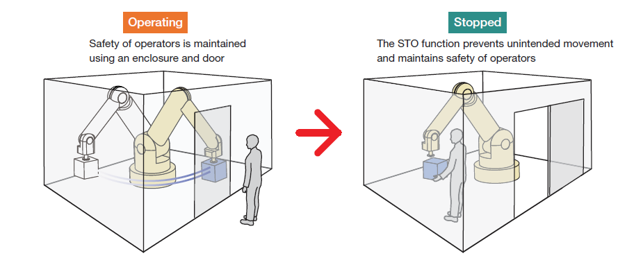
STO, or "Safe Torque Off," is a built-in safety feature that simplifies the management of safety systems in motion control applications, such as robotics. This function is essential for ensuring the safety of operators and machines by preventing unintended motor movements. As part of a comprehensive safety strategy, it helps minimize risks associated with industrial equipment.
Â
Initially developed for servo motor drivers, the STO function is a dedicated safety mechanism that stops motor motion instantly in case of an error. This feature is particularly important in environments where humans work closely with machines, like in manufacturing or assembly lines. Using a driver with an integrated STO function can reduce the need for extra components, simplify wiring, and save valuable space while enhancing operational safety.
Â
Advantages of a Built-in STO Function:
- Reduces the need for peripheral equipment
- Makes wiring simpler
- Optimizes space utilization
Â
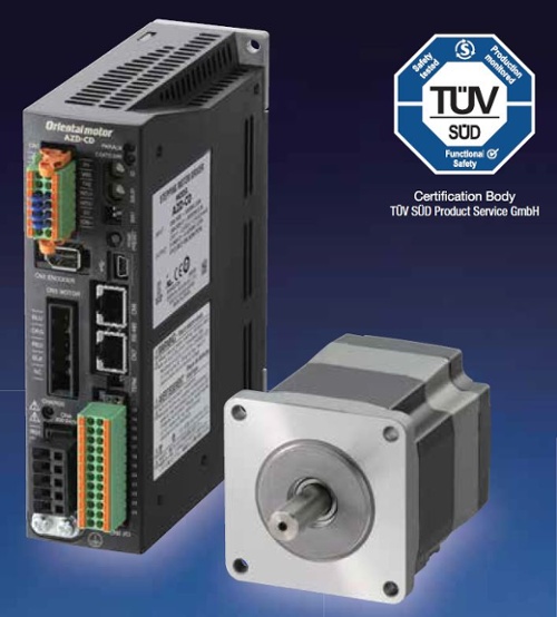
In recent years, the STO function has also become available in stepper motor drivers and variable frequency drives for AC motors. The AZ series of AC-input stepper motor drivers from Oriental Motor now includes this certified safety feature, making it easier to comply with safety standards. The AZ series STO function meets the requirements of IEC 61800-5-2 and IEC 60204-1 (Stop Category 0).
Â
Â
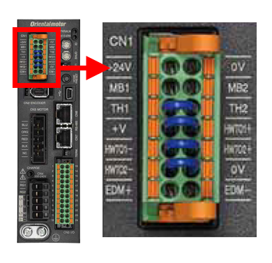
How Does It Work?
Take a look at the CN1 connector terminal and the bottom two blue jumper wires. These terminals are labeled HWTO1+, HWTO1-, HWTO2+, and HWTO2-. These two inputs are redundant, normally-closed safety inputs, which means that STO-related alarms will trigger if either input is disconnected or open. The purpose of the blue jumper wires is to prevent STO-related alarms when the driver is powered up for the first time.
Most of our I/O connections are dry contacts, meaning an external power supply is necessary to power the circuit. When the application requires the STO safety function, these blue jumper wires are removed, and the HWTO inputs are connected to an external normally closed safety circuit. By definition, they are dry contacts. However, when the jumper wires are installed and the driver is powered on, these contacts are technically considered wet contacts since they use an internal 24VDC power supply to power the circuit.
If an open circuit is detected in the safety circuit during operation, it will forcibly remove power from the motors and prevent unintended motion in the fastest and safest way possible.
Â
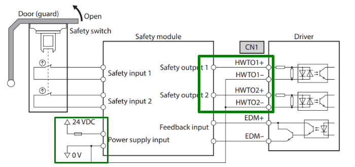
Below is a wiring diagram for an STO circuit involving a door, a safety module, and a driver.
Â
Â
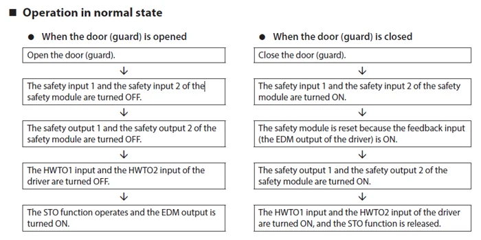
In the table below, we show how the external safety system works with our HWTO inputs in the same door application.
Â
Â
Is It Really Necessary?
When designing equipment, manufacturers (OEMs) need to conduct a risk assessment to determine the appropriate level of safety for the equipment. If the current design doesn’t meet safety standards, additional protective devices must be added. A safety system can include multiple motor drivers and other devices connected to the circuit, such as switches or buttons.
There is no absolute, guaranteed safety for robots or machinery. Every machine will eventually fail, and humans are not perfect all the time. Design engineers need to implement a safety system that minimizes the likelihood of unintended motion from the motor when it’s supposed to be stopped. This likelihood, or frequency of occurrence, is defined by the safety integrity level, or safety index. We’ll cover this in more detail later in this post.
Â
How Does It Help?
Â
Â
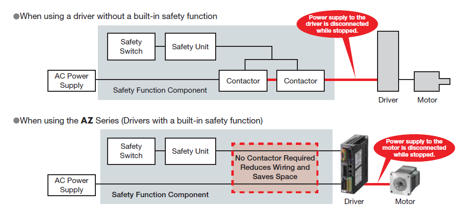
When a driver without a built-in STO safety function is used, additional contactors are necessary to cut off power to the driver and motor. When an AZ series driver with a built-in STO safety function is used, no contactors are required, and the power to the motor is cut off directly. By using an AZ series driver, wiring can be reduced and space is saved.
The STO safety circuit function is designed to be used after the motors are already in a stopped state. It is not intended to be used as an E-STOP (Emergency Stop) during normal operation. To connect safety-related equipment for additional measures, use the EDM output (from the STO circuit).
Â
| TIP : Is it better to use STO vs inputs such as C-OFF and FREE to turn off motor current? |
| Yes. The STO circuit essentially bypasses the contactors and disconnects the motor from its power directly. This effectively removes any chance of the motor unintentionally starting while it's stopped. The C-OFF and FREE inputs do offer the same function in turning the motor current off, but the difference is how fast they can do it. The STO circuit skips the I/O circuits and cuts off power to the motor directly, so it's considered faster and safer. Remember, the goal is to prevent unexpected movement as quickly as possible. |
Â
Safety Index
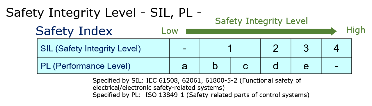
To assist OEMs in selecting the right products, device manufacturers may provide a "functional safety" specification based on the following regulatory standards. The umbrella standard, or the main standard, is the IEC 61508, followed by more specific sub-standards. The machine standard specified by IEC, IEC 62061, is designated for SIL. The machine standard specified by ISO, ISO 13849, is designated for PL. SIL and PL are categorized safety standards as specified by either IEC or ISO.
For SIL (Safety Integrity Level) and PL (Performance Level), the range of these safety ratings overlaps a bit, but they are quite similar. For example, a safety system rated for SIL 2 is the same as PL d.
Â
Â
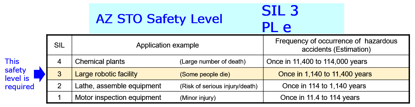
The safety level of the equipment is determined by the designer. For instance, for a large robotic facility, a large robot can potentially cause fatal harm if it moves unexpectedly while an operator is working nearby. Think of the centrifuge that astronauts use to train themselves with G forces at NASA. Imagine if someone was servicing a part of the machine, and it unexpectedly starts.
For large robots, a SIL 3 or PL e safety-rated product would be ideal. A motor driver that's rated for SIL 3 or PL e may have one failure event happen in 1,140 to 11,400 years (estimated).
Â
Â
Emergency Stop Category
Stop categories are also defined by regulatory standards. In this case, they're defined in IEC 60204-1. Stop Category 0 equates to pulling the plug to the motor. Stop Category 1 brings motors to a controlled stop, then pulls the plug. Stop Category 2 brings motors to a controlled stop and then keeps power on.
- Stop Category 0 - stopped by an uncontrolled stop and immediate removal of power
- Stop Category 1 - stopped by a controlled stop with power, then remove power when stopped
- Stop Category 2 - stopped by a controlled stop with power, then leave the power on
The STO function from the AZ series drivers is directly related to Stop Category 0 as defined by IEC 60204-1. Under Stop Category 0, a motor is stopped by forced and immediate removal of power to the machine actuators, such as an uncontrolled stop (no deceleration).
Other similar acronyms for similar safety functions are SS1 (Safe Stop 1), SS2 (Safe Stop 2), SOS (Safe Operation Stop), SSE (Safe Stop Emergency), and SBC (Safe Brake Control). Of these, only STO is rated for Stop Category 0, SS1 is rated for Stop Category 1, and SS2 is rated for Stop Category 2.
Â
Safety Standards and Applicable Products
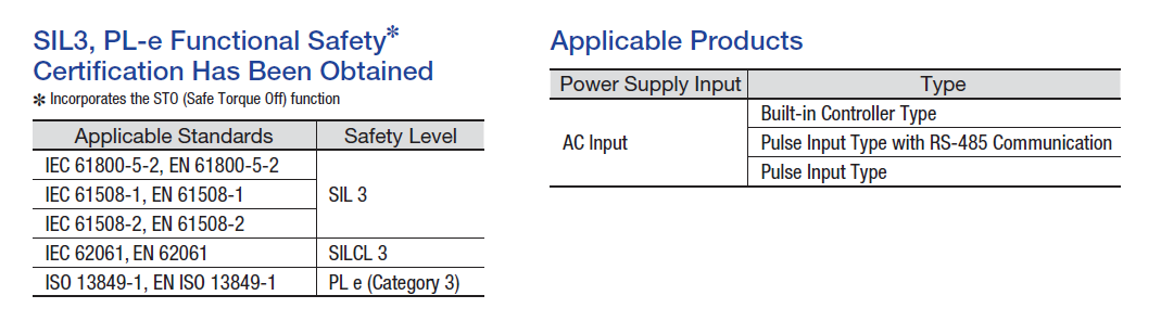
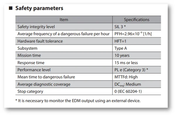
The applicable standards for the STO circuit are IEC 61800-5-2, EN 61800-5-2, IEC 61508-1, EN 61508-1, IEC 61508-2, EN61508-2, IEC 62061, EN 62061, ISO 13849-1, and EN/ISO 13849-1. The STO function of the AZ series driver is rated for SIL 3 and PL e (Category 3).
The STO circuit is a built-in function of AZ series drivers including built-in controller type, pulse input type with RS-485 communication, and pulse input type.
Â
Here are the safety parameters for the AZ series drivers with built-in STO circuit function. The average frequency of a dangerous failure per hour (PFH = 2.96x10^-9). The safety integrity level is SIL 3. The performance level is PL e, and the stop category is 0. This is better than some other STO functions offered in the industry.
Â
Â
| The STO circuit function should not be used for an emergency stop to stop the motors. It is designed to be used after motion has ceased completely. Once this happens, activating the STO circuit would ensure that power is cut off from the motor thus keeping operators safe while they service a robot or machine. If an emergency stop is necessary, please wire a button as part of the external safety equipment. |  |
Â
Please download our new AZ Series STO Brochure!
 hbspt.cta._relativeUrls=true;hbspt.cta.load(2284573, '3adb44c2-2317-49ed-8159-f978b3f3d4cb', {"useNewLoader":"true","region":"na1"});
Â
The AZ series AC-input drivers with built-in STO circuit function are certified by TÃœV SÃœD Product Service GmbH and can be used with any AZ series "AC-input" stepper motors, linear actuators, and rotary actuators. Once the motor or actuator is connected, the driver automatically adjusts its internal settings to match the motor (or actuator). Don't forget the RGB100 regeneration resistor accessory to prevent damage to the drivers due to regenerative voltage.
For additional information about the STO function, please refer to the AZ series "functions" manual, or contact us for details. The STO function is also available with AZ Series AC input EtherNet/IP or EtherCAT type drivers.
 hbspt.cta._relativeUrls=true;hbspt.cta.load(2284573, '9dc8f9b1-c764-4b71-a801-09f51c28a089', {"useNewLoader":"true","region":"na1"});
 hbspt.cta._relativeUrls=true;hbspt.cta.load(2284573, '4c361ccd-45b7-4a05-ae1c-ea16a49b5059', {"useNewLoader":"true","region":"na1"});
Thank you for reading. Please subscribe to receive new posts.
Â
"A Heat Exchanger Unit is a device used to transfer thermal energy (heat) between two or more fluids. Heat exchangers are used in a wide variety of applications, such as heating and cooling of buildings, industrial processes, and power generation.
The heat exchanger unit essentially consists of heat exchangers such as Plate Heat Exchanger, Shell and Plate Heat Exchanger, or other counterpart, a circulating pump, a fluid make-up pump, thermometers, a filter, sensors, a pipeline and valves. It is also possible to design a temperature control system, pressure stabilization system, variable-frequency controller, heat metering and communication controller, etc. according to the client`s requirements.
Big advantage of heat exchanger unit is that, by adopting a modularized structure, it maximizes each component`s function to the most. The precise control for heat exchange process also saves time and efforts for maintenance and installation.
Feature is that intelligent control, excellently energy-saving, high automation and easy to operate, high cost performance and wide application.
Heat Exchanger Unit,Heat Exchanger Ac Unit,Heat Exchanger Package Unit,Heat Recovery Ventilation Unit
Guangdong Jiema Energy Saving Technology Co.,Ltd , https://www.jmheatexchanger.com