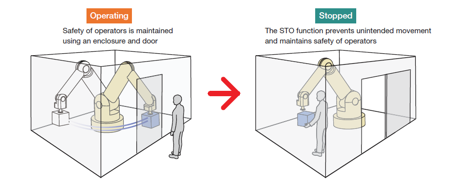
STO, or "Safe Torque Off," is a specialized safety feature integrated into motor controllers and drivers to enhance operational safety. It serves as a critical safeguard against unintended motor motion, particularly in industrial applications like robotics. This built-in safety mechanism helps prevent accidents and damage, ensuring the safety of operators and machinery alike.
Â
Initially introduced in servo motor drivers, the STO function became a vital component of motor control systems. It ensures that motors remain stationary unless specifically commanded to move. This feature is crucial in environments where human interaction with machinery is common, such as in manufacturing facilities or robotics workspaces. By eliminating the need for external safety equipment, drivers with an integrated STO function reduce complexity, save space, and improve overall reliability.
Â
Advantages of Built-in STO Functions:
- Reduces the need for extra safety hardware
- Simplifies wiring configurations
- Optimizes space usage
Â
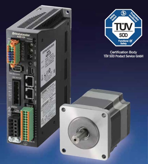
Over the past few years, the STO function has also been adopted by stepper motor drivers and variable frequency drives (VFDs) for three-phase AC motors. The AZ series AC-input stepper motor drivers from Oriental Motor now come equipped with this certified safety feature, making safety management simpler and more efficient. The AZ series meets the stringent requirements of IEC 61800-5-2 and IEC 60204-1 (Stop Category 0).
Â
Â
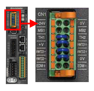
How Does It Work?
Take a look at the CN1 connector terminal and the two blue jumper wires located at the bottom. These terminals are labeled HWTO1+, HWTO1-, HWTO2+, and HWTO2-. These inputs serve as redundant, normally-closed safety inputs, meaning that any disconnection or open circuit in either input will trigger STO-related alarms. The purpose of the blue jumper wires is to prevent accidental triggering of STO alarms when the driver is first powered up.
Most of our I/O connections are dry contacts, requiring an external power supply to operate. In applications where the STO safety function is needed, the blue jumper wires are removed, and the HWTO inputs are connected to an external normally closed safety circuit. This makes them dry contacts by definition. However, when the jumper wires are installed and the driver is powered on, these contacts become wet contacts since they rely on an internal 24VDC power supply.
In the event of an open circuit in the safety circuit during operation, the motor’s power is immediately cut off, ensuring the fastest and safest response possible to prevent unintended motion.
Â
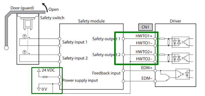
Below is a wiring diagram for an STO circuit involving a door, a safety module, and a driver.
Â
Â
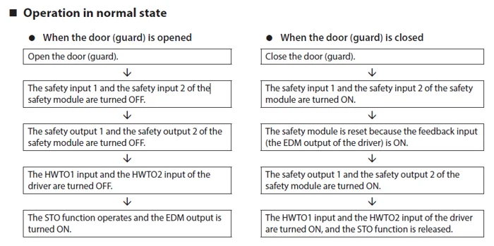
In the table below, we illustrate how the external safety system interacts with our HWTO inputs in the same door application.
Â
Â
Is It Really Necessary?
When designing machinery, manufacturers (OEMs) must conduct a risk assessment to determine the appropriate safety level for their equipment. If the initial design fails to meet safety standards, additional protective devices must be incorporated. A safety system might involve multiple motor drivers and other devices connected to the circuit, such as switches or buttons.
No machine is absolutely guaranteed to be safe. All machines will eventually fail, and humans are not infallible. Engineers must implement a safety system that minimizes the likelihood of unintended motor motion when the machine is stopped. This probability, or frequency of occurrence, is defined by the safety integrity level or safety index. We’ll explore this further in the next section.
Â
How Does It Help?
Â
Â
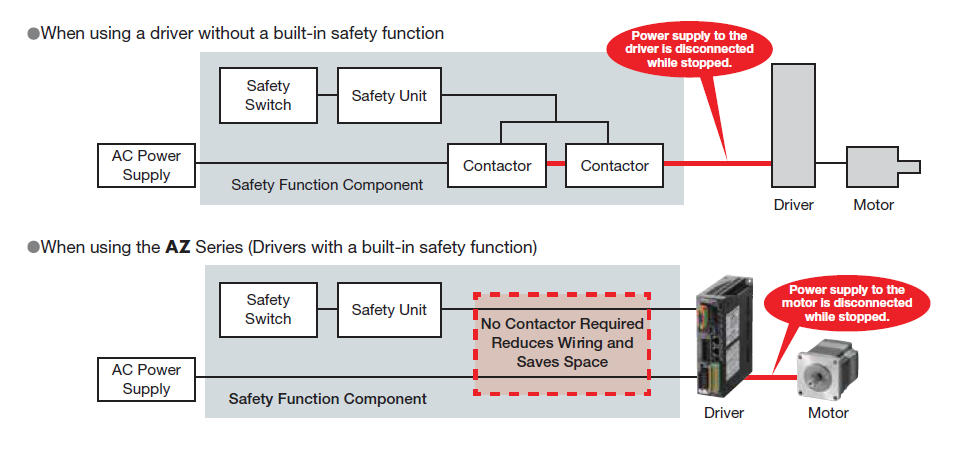
When using a driver without a built-in STO safety function, additional contactors are necessary to cut off power to both the driver and the motor. However, when an AZ series driver with a built-in STO safety function is employed, no contactors are required. Power to the motor is cut off directly, reducing wiring and saving valuable space.
The STO safety circuit function is designed to be used after the motors have already stopped moving. It is not intended to replace an emergency stop (E-STOP) during normal operation. To incorporate additional safety-related equipment, use the EDM output (from the STO circuit).
Â
| TIP : Is it better to use STO instead of inputs like C-OFF and FREE to turn off motor current? |
| Absolutely. The STO circuit essentially bypasses the contactors and disconnects the motor from its power source directly. This eliminates any chance of the motor unintentionally starting while it's stopped. While the C-OFF and FREE inputs also turn off the motor current, the key difference lies in speed. The STO circuit skips the I/O circuits and cuts off power to the motor directly, making it faster and safer. The goal is to prevent unexpected movement as quickly as possible. |
Â
Safety Index
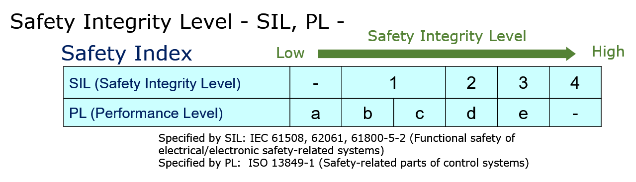
To help OEMs choose the right products, device manufacturers often provide a "functional safety" specification based on the following regulatory standards. The overarching standard is IEC 61508, followed by more specific sub-standards. The machine standard specified by IEC, IEC 62061, is associated with SIL. The machine standard specified by ISO, ISO 13849, is linked to PL. Both SIL and PL represent safety ratings as specified by IEC or ISO.
For SIL (Safety Integrity Level) and PL (Performance Level), the ranges of these safety ratings overlap somewhat but are quite similar. For instance, a safety system rated for SIL 2 is equivalent to PL d.
Â
Â
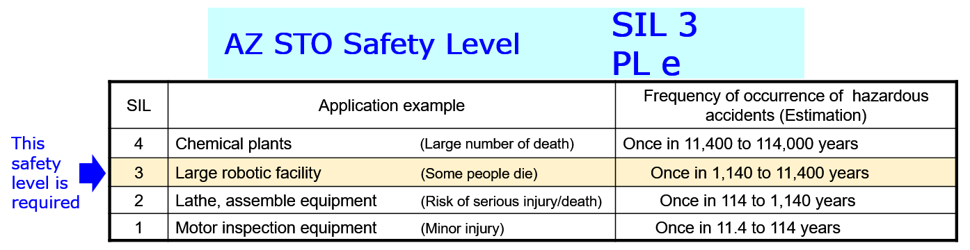
The safety level of the equipment is determined by the designer. For example, in a large robotic facility, a malfunctioning large robot could potentially cause harm if it moves unexpectedly while an operator is nearby. Consider the centrifuge used by astronauts at NASA to simulate G-forces. Imagine what could happen if someone were servicing a part of the machine, and it unexpectedly started up.
For large robots, a SIL 3 or PL e safety-rated product would be ideal. A motor driver rated for SIL 3 or PL e might experience only one failure event every 1,140 to 11,400 years (estimated).
Â
Â
Emergency Stop Categories
Stop categories are also defined by regulatory standards, specifically IEC 60204-1. Stop Category 0 corresponds to unplugging the motor. Stop Category 1 involves bringing the motor to a controlled stop before unplugging it. Stop Category 2 stops the motor with power still on.
- Stop Category 0 - Stopped by an uncontrolled stop and immediate removal of power
- Stop Category 1 - Stopped by a controlled stop with power, then removing power upon stopping
- Stop Category 2 - Stopped by a controlled stop with power, then leaving power on
The STO function from the AZ series drivers aligns with Stop Category 0 as defined by IEC 60204-1. Under Stop Category 0, a motor is stopped by forcing an immediate removal of power to the machine actuators, resulting in an uncontrolled stop (no deceleration).
Other similar acronyms for safety functions include SS1 (Safe Stop 1), SS2 (Safe Stop 2), SOS (Safe Operation Stop), SSE (Safe Stop Emergency), and SBC (Safe Brake Control). Among these, only STO is rated for Stop Category 0, SS1 is rated for Stop Category 1, and SS2 is rated for Stop Category 2.
Â
Safety Standards and Applicable Products
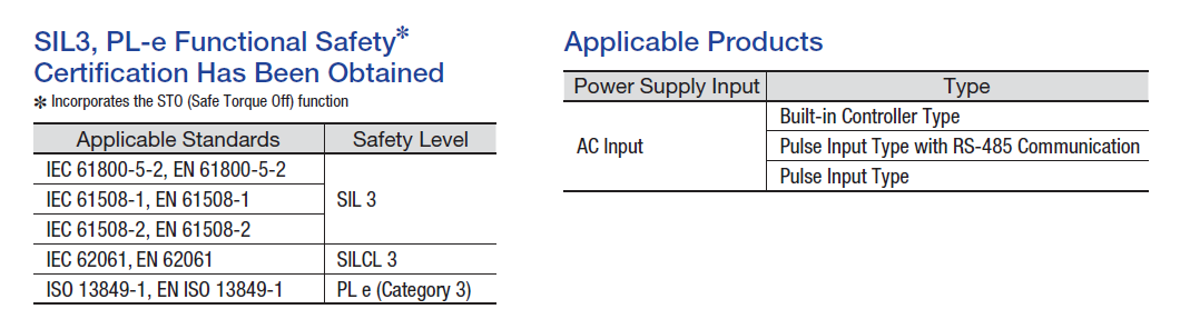
The applicable standards for the STO circuit are IEC 61800-5-2, EN 61800-5-2, IEC 61508-1, EN 61508-1, IEC 61508-2, EN 61508-2, IEC 62061, EN 62061, ISO 13849-1, and EN/ISO 13849-1. The STO function of the AZ series driver is rated for SIL 3 and PL e (Category 3).
The STO circuit is a built-in feature of AZ series drivers, including built-in controller types, pulse input types with RS-485 communication, and pulse input types.
Â
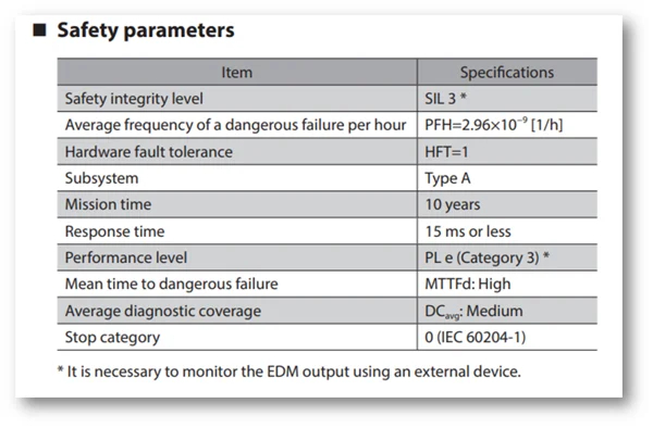
Here are the safety parameters for the AZ series drivers with the built-in STO circuit function. The average frequency of a dangerous failure per hour (PFH = 2.96x10^-9). The safety integrity level is SIL 3. The performance level is PL e, and the stop category is 0. This surpasses many other STO functions available in the market today.
Â
Â
| The STO circuit function should not be used as an emergency stop to halt the motors. It is designed to be used after the motion has completely ceased. Activating the STO circuit ensures that power is cut off from the motor, keeping operators safe while they service a robot or machine. If an emergency stop is necessary, please wire a button as part of the external safety equipment. |  |
Â
Download our new AZ Series STO Brochure today!
 hbspt.cta._relativeUrls=true;hbspt.cta.load(2284573, '3adb44c2-2317-49ed-8159-f978b3f3d4cb', {"useNewLoader":"true","region":"na1"});
Â
The AZ series AC-input drivers with the built-in STO circuit function are certified by TÜV SÜD Product Service GmbH and can be used with any AZ series "AC-input" stepper motors, linear actuators, and rotary actuators. Once the motor or actuator is connected, the driver automatically adjusts its internal settings to match the motor (or actuator). Don’t forget to pair it with the RGB100 regeneration resistor accessory to prevent damage to the drivers due to regenerative voltage.
For more information about the STO function, please refer to the AZ series "functions" manual, or contact us for details. The STO function is also available with AZ Series AC input EtherNet/IP or EtherCAT type drivers.
 hbspt.cta._relativeUrls=true;hbspt.cta.load(2284573, '9dc8f9b1-c764-4b71-a801-09f51c28a089', {"useNewLoader":"true","region":"na1"});
 hbspt.cta._relativeUrls=true;hbspt.cta.load(2284573, '4c361ccd-45b7-4a05-ae1c-ea16a49b5059', {"useNewLoader":"true","region":"na1"});
Thank you for reading. Please subscribe to receive new posts.
Â
"Flanges are a method of connecting pipes, valves, pumps, and other equipment to form a piping system, usually by welding or threading. It is also easy to clean, inspect or modify. Flanges are usually welded or tightened. Flange joints are made by bolting two flanges together and using washers between them to provide a seal.
Pipe assemblies may be bolted together between flanges. Flanges are used to connect pipes to each other, to valves, to fittings, and to special items such as filters and pressure vessels. Cover plates can be connected to create "blind flanges". Flanges are bolted together, and sealing is usually done using washers or other methods. Industries dealing with flammable, volatile, toxic or corrosive substances require special protection at flange joints. Flange shields can provide an additional level of protection to ensure safety.
There are many different flange standards worldwide. For simple functionality and interchangeability, these designs have standardized dimensions. Common world standards include ASA/ASME (USA), PN/DIN (Europe), BS10 (UK/Australia) and JIS/KS (Japan/Korea).
In most cases, standards are interchangeable, as most local standards have been aligned with ISO standards.
Flanges are also made in standardized sizes, usually in "flat", "convex", "mortise" or "ring joint" styles, but other ambiguous styles may be available.
Flange designs include "weld neck", "socket", "lap", "socket weld", "thread" and "blind flange".
Welding Neck,Neck Flange,Weld Neck Flange,Long Welding Neck Flange
Guangdong Jiema Energy Saving Technology Co.,Ltd , https://www.jmheatexchanger.com