Encoder feedback is crucial for closed-loop motion control, enhancing precision, reliability, and efficiency in machinery and robotics. In this article, we'll explore how optical, magnetic, and capacitive encoders function and offer some tips for choosing the right one.
What's covered?
- How Do Encoders Work?
- Optical Encoders: Most Common
- Magnetic Encoders: Emerging
- Capacitive Encoders: Newest
- The Case for Magnetic Encoders
- 10 Things to Consider When Choosing Optical vs Magnetic vs Capacitive Encoders
- FYI: Multi-Turn Mechanical Absolute Encoder
Â
|
|
 |
Â
How Do Encoders Work?
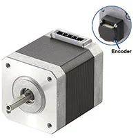
An encoder is typically mounted on the rear shaft of a motor. It senses the shaft's rotation as it moves. While both optical and magnetic encoders are similar in principle, this article will primarily focus on rotary encoders rather than linear ones.
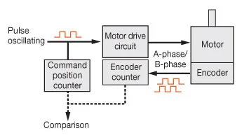
The method each type of encoder uses to track shaft rotation varies, but they all produce a pulsetrain signal as the motor shaft rotates. By performing some simple math, the number of pulses can indicate the location of the motor shaft and how far it has rotated from its home position. For instance, if the encoder resolution is 200 pulses per revolution and the encoder outputs 200 pulses, then you know the motor shaft has completed one full revolution. The frequency of the pulses, measured in Hz (or pulses per second), can tell you how fast the motor shaft is rotating. The direction is determined by monitoring which channel of pulses is leading the other (A or B-phase). That’s the basic explanation.
Â
Understanding what to do with the pulses is the next step. Here’s a video that demonstrates how an encoder is used in a diverting conveyor application that uses a stepper motor.
Â
Â
Let’s now take a closer look at the different types of encoders and how they work.
Â
Optical Encoders: Most Common
Optical encoders are the most widely used type of encoders and offer the highest precision, accuracy, and resolution. Since the light emitter and light receiver are electrically operated, they require a continuous power supply to function.
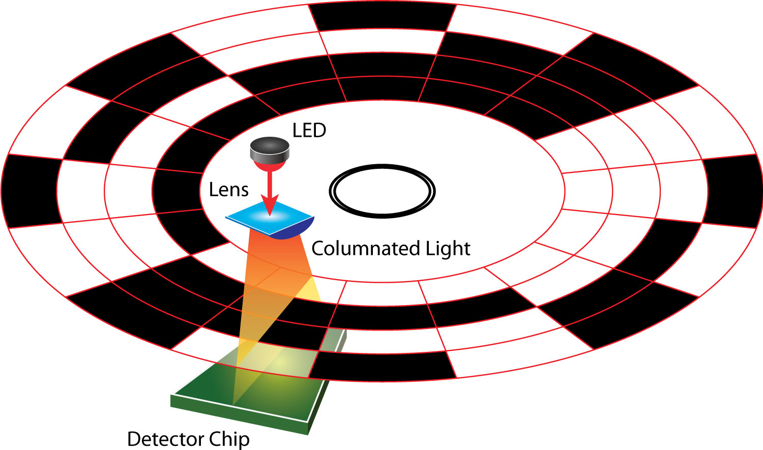
In a traditional "transmissive" optical encoder, typically mounted on the rear shaft of stepper motors, brushless motors, or servo motors, the main components include a light emitter (like an LED), a code wheel, a light receiver (photodetector), a power circuit, and an output circuit. With these three components, motion can be sensed by the following method:
Â
| The code wheel is a wheel with slits cut out near the outside of the wheel. As the code wheel is rotated by the motor shaft, the light from the stationary light emitter either passes through the slits in the code wheel or is blocked by it. This provides a continuous stream of binary on/off "pulses" of light from the photodetector's perspective, and the output circuit outputs an ON signal when the light shines through, and an OFF signal when the light is blocked. A motor driver, PLC, or HMI typically interprets the pulsetrain signal and can convert it to steps, degrees, inches, or millimeters for easier understanding of where the motor shaft is and how fast it's moving. Additional measures, such as position correction, can be performed on the fly. |
Source: US Digital |
There are several classifications of optical encoders, as explained below.
Â
Transmissive or Reflective?
Traditionally, optical encoders are the transmissive type, meaning the LED light must shine through the transmissive disk (code wheel) and then reach the photodetector. In recent years, the transmissive disk has been replaced by a reflective disk to save space.
Â
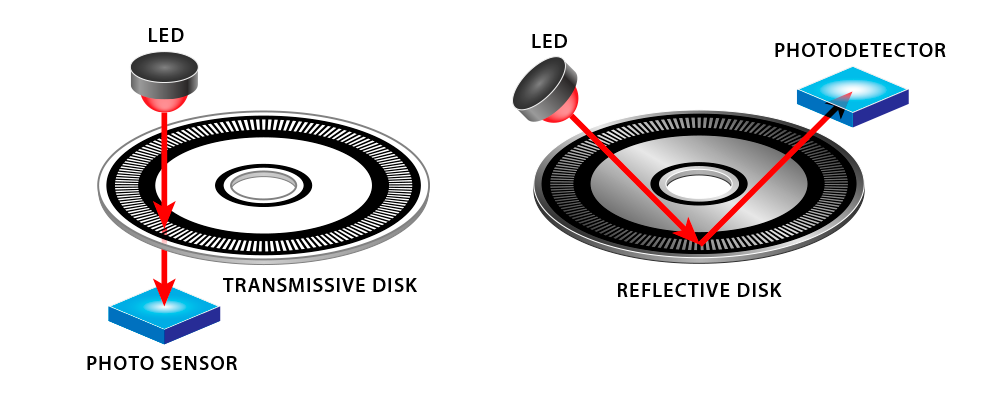
Source: US Digital
Â
Incremental or Absolute?
|
Incremental encoders detect and output a pulsetrain signal but can only track changes in relation to a home position. The reason is that the code wheel inside an incremental encoder does not provide any unique position values, as every position value is treated the same. If you have a third Z or index channel, then there is one absolute position that can be used to reference a home starting position or count revolutions. If you look at a code wheel of an incremental encoder, every slit looks the same. If power is lost, the position information is also lost, and the motor or linear actuator will need to perform a homing operation to start counting pulses from the beginning; often requiring a restart of the machine. Incremental encoders are typically more affordable and suitable for applications where absolute position feedback isn’t critical, such as in speed control systems where it's more important to track velocity and acceleration. |
Source: US Digital |
|
Source: US Digital |
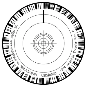
Since the code wheel of an absolute encoder has a unique pattern for each position and can provide multiple "bits" of information, it can provide a unique position value over a full rotation or stroke. As the motor shaft rotates, sensors read the coded pattern to determine the absolute position. This allows the controller to know the exact position at any given time, even after a power loss. Absolute encoders are essential for applications where position accuracy and repeatability are critical, such as in robotics, CNC machines, and precision automation. However, absolute encoders are more expensive than incremental encoders. Many absolute encoders provide position information with an accuracy of ±1 degree or better over a full rotation. Some absolute linear encoders can achieve position accuracy of just a few microns over the full stroke. |
Â
Magnetic Encoders: Emerging
|
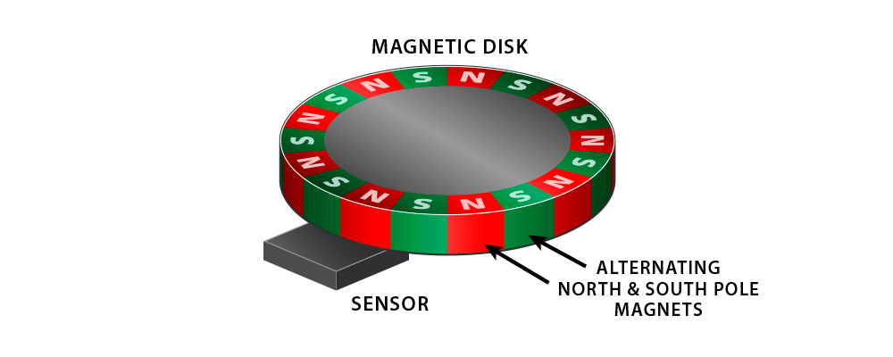
Magnetic encoders do not use a light emitter or a light receiver but still use a code wheel and a sensor. Instead of slits, the code wheel has alternating north and south pole magnets on the outer edge of the code wheel. The magnetic sensor senses changes in magnetic polarity when the poles pass by. The end result is the same as the output circuit outputs pulses to a PLC or HMI. Since there's no need to power the light emitter and receiver, the magnetic encoder uses less power than an optical encoder. |
Source: US Digital |
Magnetic encoders are more robust than optical encoders in terms of operating in humid, dusty, or dirty environments. However, magnetic encoders may not work well in environments with magnetic interference. Magnetic encoders are also available in rotary, linear, incremental, and absolute types. To enable a magnetic encoder to track absolute positions, multiple magnetic disks are necessary.
Â
Capacitive Encoders: Newest
|
Source: US Digital |
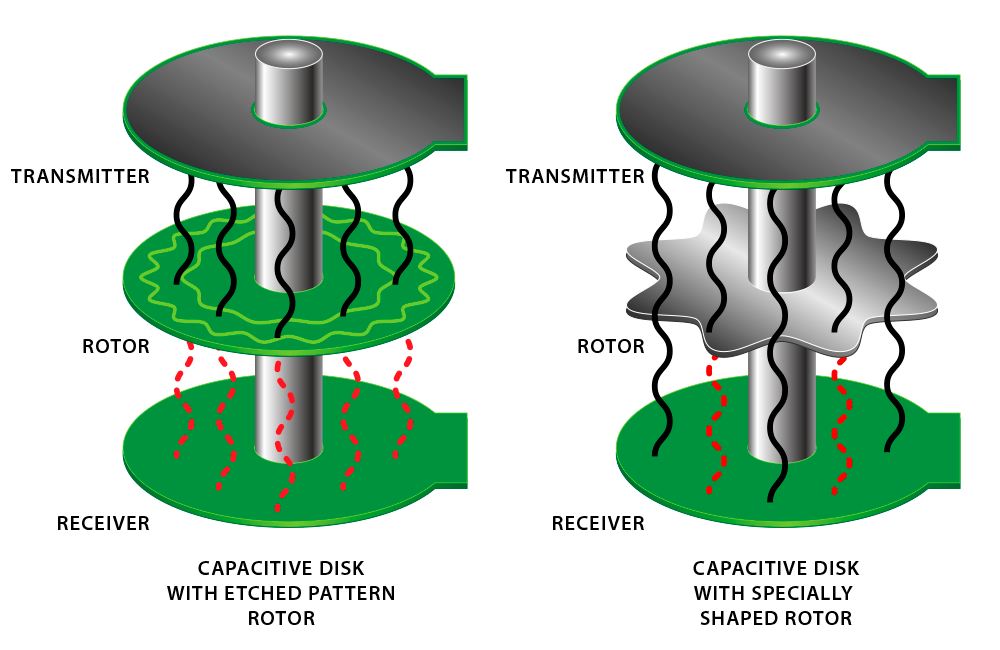
Capacitive encoders use a newer technology that offers the same environmental benefits as magnetic encoders. According to US Digital, this type of encoder detects changes in capacitance using a high-frequency reference signal and then converts the signal into pulses. The structure includes a transmitter, a rotor, and a receiver. The rotor typically has a pattern etched into it or has a uniquely shaped design. When the rotor moves in between the transmitter and the receiver, the pattern modulates the high-frequency signal generated by the transmitter. The receiver is able to read the modulated signal and translate it to a pulse signal. Â |
Like optical encoders, capacitive encoders are susceptible to noise and electrical interference, so sometimes additional preventative measures have to be made. Capacitive encoders also have a low current draw. Capacitive encoders are also available in rotary, linear, incremental, and absolute types. To enable a capacitive encoder to track absolute positions, multiple capacitive disks are necessary.
Â
"
Single pilot operated check valve, Pilot check valves, Hydraulic Check Valves
Huaian Hy-waloil Machinery Co.,Ltd , https://www.hywaloil.com